GD&T is the universal language of engineers and product designers. They use this symbolic language to communicate their product design drawings with manufacturer and other professionals involved in the product design. When a hobbyist needs a simple part for a product design, he might use his 3D-printer or lathe machine to produce it in a matter of minutes. Since he is all-in-one designer, manufacturer & inspector he does not need technical drawings.
In commercial manufacturing, however, the designer(s), manufacturer(s) and inspector(s) are rarely the same person and may even work at different companies and different regions, each performing their respective tasks in different time-frames. Thus there is a need to have product design specifications and technical drawings to accurately communicate the intended design among different parties involved in the product design and manufacturing processes.
If you’re new to GD&T, we advise you to read our introductory article on Geometric Dimensioning & Tolerancing. In this article, we cover the basics of Geometric Dimensioning and Tolerancing. You can consider taking a GD&T Training to get your mechanical engineering career to the next level.
Basics of Geometric Dimensioning and Tolerancing (GD&T)
It’s important to note that GD&T is not a creative design tool; it can’t suggest how certain parts of the design should be controlled or what should be the dimension of a specific part. It can’t communicate a design intent or the intended function of a part in the design. Instead, it’s the design engineer’s responsibility to accurately translate his hopes and intentions into unambiguous and gauge-able specifications.
We’ll discuss the following essential GD&T basic concepts:
- GD&T Symbols
- Feature Control Frames
- Basic Dimensions
- Datums and Features
- Material Condition
GD&T Symbols
As stated earlier, GD&T is a language used by engineers to communicates the specification and intent of the design with other parties. Using English or other language for the design specifications has serious shortcomings and can’t convey the message of designer. Thus, instead of English language, GD&T takes advantage of meaningful symbols in design specification drawings.
The following figure shows an example of GD&T symbol used for flatness.

Symbols are better, because of the following reasons:
- Anyone can read, write and understand symbols regardless of their language
- Symbols can be placed close to where they apply in drawings
- Each symbol carries a specific meaning and is easy to draw
- Symbols are easier to spot visually
Feature Control Frames
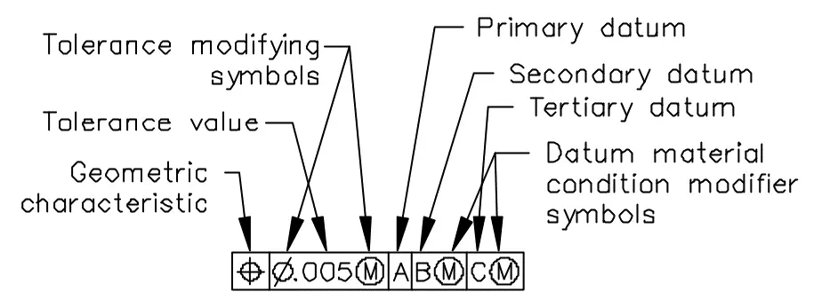
Feature Control Frame is a rectangular sign which is used to convey the geometric control for a feature on the drawing. A feature control frame is made of compartments which carries the following information:
- Geometric characteristic symbol (control symbol)
- Tolerance zone type and value
- Tolerance zone modifiers
- Datum references (if required)
Basic Dimensions
A basic dimension in a drawing is a numerical value used to specify the theoretically exact size, profile, orientation, or location of a feature or datum target. The value is usually enclosed in a rectangular frame, as shown in the following figure:

Given that there is only one value in the box, this basic dimension doesn’t have tolerance. In case there is tolerance for the basic dimension, its value is specified in feature control frames, notes, or in other toleranced dimensions.
Datums and Features
A datum is the origin from which the location or geometric characteristics of features of a part are established. Datum is the reference point which tell us where to measure from. A datum reference is an alpha letter appearing in a compartment following the geometric tolerance in a feature control frame. It specifies a datum to which the tolerance zone or acceptance boundary is basically related.
Material Condition
Material condition is another way of thinking about the size of an object taking into account the object’s nature. Material condition is simply a simple description of a feature’s size in the context of its intended function.
Well, this is a lot to take in, and we’re not trying to completely describe every aspect of the basic concepts here. Rather, we will explain the concepts further in separate articles.