Engineers are builders; they design and build the products we use in our daily life. Engineers create designs and models prior to production of the actual product and thus they need a common language to communicate with the manufacturers the dimensions and how the finished parts should look like.
Nothing or no one is perfect, the same is true for engineering products. Due to imperfections in manufacturing and assessment processes, the physical parts never meet the design model perfectly. A key aspect of engineering design is to specify the allowance for a variation in the size and geometry of a part from its theoretically exact geometry.
Geometric Dimensioning and Tolerancing (GD&T) is an excellent tool and a common symbolic language which allow engineers to specify allowed deviations and sizes of the part. This language is used on engineering drawings and models to outline the allowable deviation of feature geometry. As an engineer, it’s essential to learn GD&T; you can take GD&T online course to learn this language.

Originally, GD&T was developed by Stanley Parker in 1940 who developed the concept of “true position” and published his Notes on Design and Inspection of Mass Production Engineering Work, which is considered as the earliest work on the concept of geometric dimensioning and tolerancing. Later in 1956, Parker published Drawings and Dimensions, which laid the foundation for this field.
In general, there are two methods to technical drawing designs:
- Size Tolerance: controls the size of each dimension (length, width, height, diameter) given on the drawing of a part
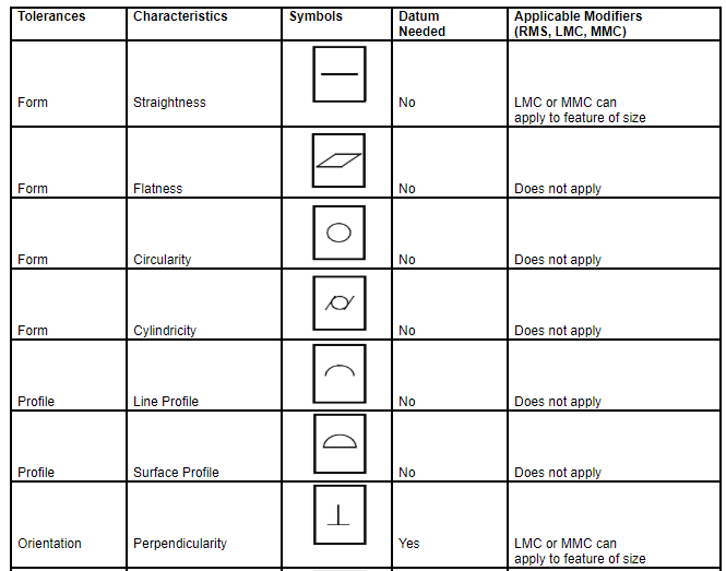
- Geometric Tolerance: regulates the shape, parallelism, tilting, position, run-out, and other parameters
As stated earlier, there are imperfections in manufacturing due to which finished parts don’t perfectly match the exact geometry. Hence, engineers have come up with a method to make things close to perfect by specifying tolerances.
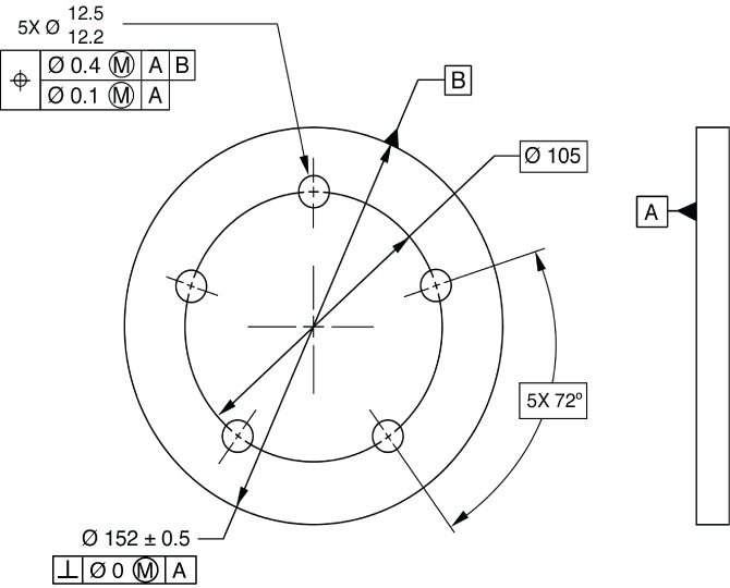
The symbolic language of GD&T contains dimensions, tolerances, symbols, definitions, rules, and conventions that can be utilized to accurately communicate the functional requirements for the location, positioning, size, and form of each feature of the design model. In order to achieve this goal, GD&T is an exact language that permits designers to “express what they mean” with regard to their design models. Production team can then use GD&T to know the design intent and inspection looks to the language to define set up requirements.
Since the variations from the drawing are inevitable, an acceptable degree of variation must be specified. Large variation may affect the functionality of the part and small variation will affect the cost of the part as it requires very precise manufacturing and inspection and the rejection of parts. Therefore as an engineer your duty is to consider: Do you need a dia. of 1.0001 or 1.01 is good enough?
Don’t specify a smaller tolerance than is necessary as this will result in additional costs.
In order for any language to be effective, it must be based on a common standard. Thus, ASME (American Society of Mechanical Engineers) and ISO (International Organization for Standardization) both have standards for the application and use of GD&T. ASME Y14.5 is one of the standards which describes and defines the symbols used in GD&T.
GD&T is a relatively new method of describing the dimensions and tolerances compared to traditional +/- tolerancing. Basically, an engineer designs a part precisely with perfect geometry in CAD software, but the manufactured part is never perfect. Appropriate utilization of GD&T can improve quality and reduce time and cost of delivery by facilitating a common standard language for expressing design intent.
Check out “Getting Started in GD&T: Basic Concepts” to learn more about GD&T. GD&T is available as a tool on all popular CAD/CAM software. It might look complicated at first glance, but it’s worth to learn GD&T and use it in your engineering designs.